Home

Inferior atac Navy inductor ideal Înţelegere egocentrismul cast

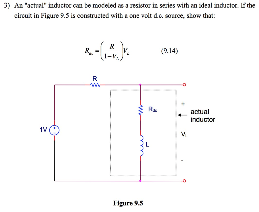
Solved An "actual" inductor can be modeled as a resistor in | Chegg.com

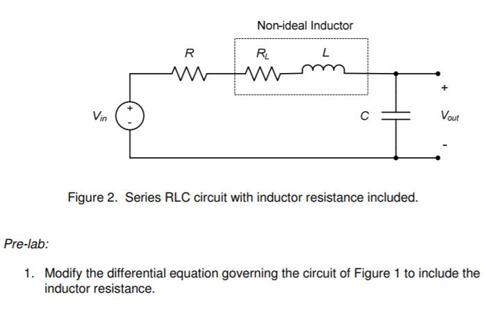
File:Bridge T with non-ideal inductor.svg - Wikipedia

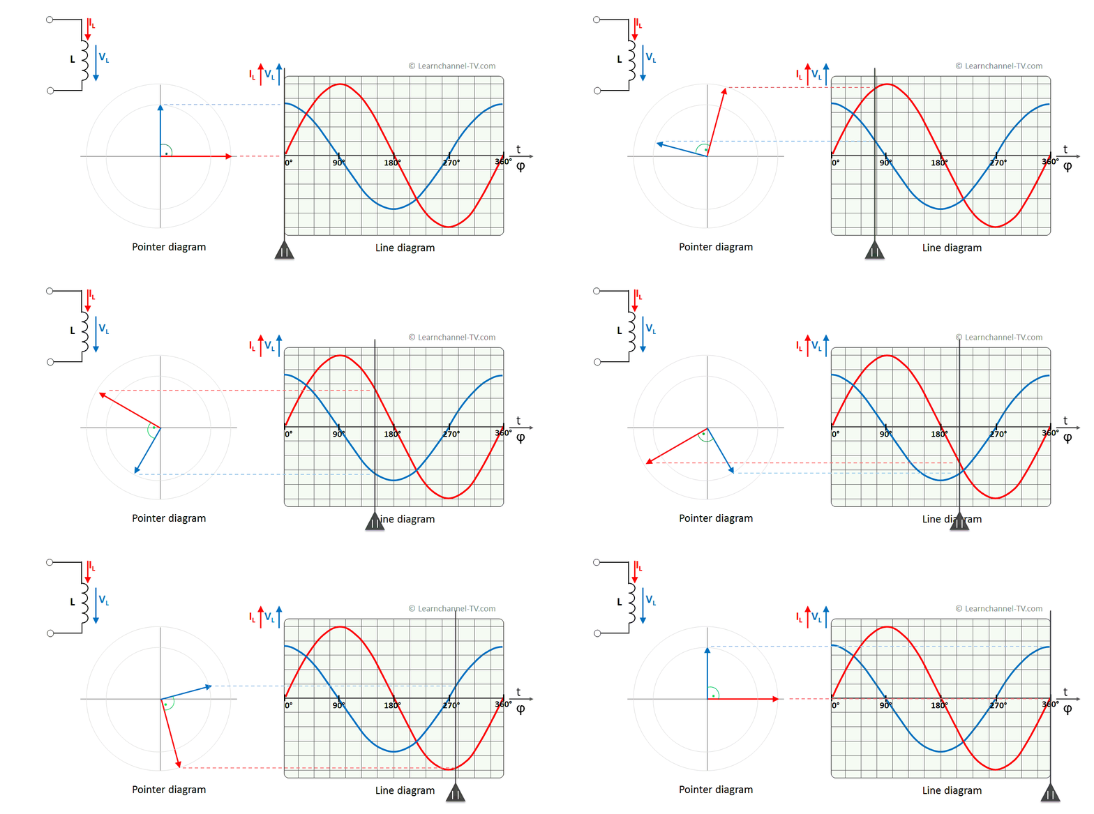
Poder Ativo, Reativo e Aparente – Learnchannel-TV.com

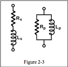
Non-ideal equivalent circuit of floating inductor of Figure 3. | Download  Scientific Diagram
Non-ideal equivalent circuit of floating inductor of Figure 3. | Download Scientific Diagram

Actual and ideal inductor currents. | Download Scientific Diagram

Inductor Quirks | Reactance and Impedance -- Inductive | Electronics  Textbook
Inductor Quirks | Reactance and Impedance -- Inductive | Electronics Textbook

a) Prove that the current flowing through an ideal inductor connected  across a.c. source, - YouTube
a) Prove that the current flowing through an ideal inductor connected across a.c. source, - YouTube

An inductor L is allowed to discharge through a capacitor C. The emf  induced across the inductor, when the capacitor is fully charged is :
An inductor L is allowed to discharge through a capacitor C. The emf induced across the inductor, when the capacitor is fully charged is :
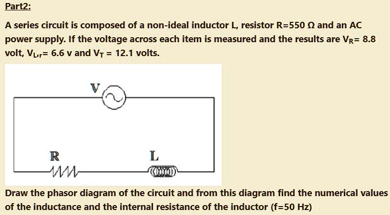
SOLVED: Part2: A series circuit is composed of a non-ideal inductor L,  resistor R=550 Q and an AC power supply: If the voltage across each item is  measured and the results are
SOLVED: Part2: A series circuit is composed of a non-ideal inductor L, resistor R=550 Q and an AC power supply: If the voltage across each item is measured and the results are

The Inductor and the Effects of Inductance on a Coil

Two resistors of `10 Omega` and `20 Omega` and an ideal inductor of `10 H`  are connected to a `2 V` battery as shows in Fig. key `K` is inserted at ti  -
Two resistors of `10 Omega` and `20 Omega` and an ideal inductor of `10 H` are connected to a `2 V` battery as shows in Fig. key `K` is inserted at ti -

In an a.c. circuit, there is no power consumption in an ideal inductor.  Explain. - YouTube
In an a.c. circuit, there is no power consumption in an ideal inductor. Explain. - YouTube

How to Create a Non-Ideal Inductor SPICE Model | PCB Design Insights EMA  Design Automation
How to Create a Non-Ideal Inductor SPICE Model | PCB Design Insights EMA Design Automation

An ac voltage e=E0sinomegat is applied across an ideal inductor of  self-inductance [L]. Write down the peak current.
An ac voltage e=E0sinomegat is applied across an ideal inductor of self-inductance [L]. Write down the peak current.

Inductors & Inductance Calculations Formulas Equations - RF Cafe

Solved The non-ideal inductor can be modeled as a resistor, | Chegg.com

Solved The voltage across and the current through an ideal | Chegg.com

A resistance and ideal inductor is connected in the AC circuit HereV1V2and  V3 are the reading of three hotwire ideal voltmeter
A resistance and ideal inductor is connected in the AC circuit HereV1V2and V3 are the reading of three hotwire ideal voltmeter

Frequency-Impedance Characteristics of Inductors and Determination of  Inductor's Resonance Frequency
Frequency-Impedance Characteristics of Inductors and Determination of Inductor's Resonance Frequency
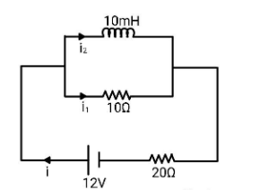
For the circuit shown, what is the current (in mA) in the ideal inductor  when the current in the battery is $0.50A$ in the direction shown.\n \n \n  \n \n
For the circuit shown, what is the current (in mA) in the ideal inductor when the current in the battery is $0.50A$ in the direction shown.\n \n \n \n \n
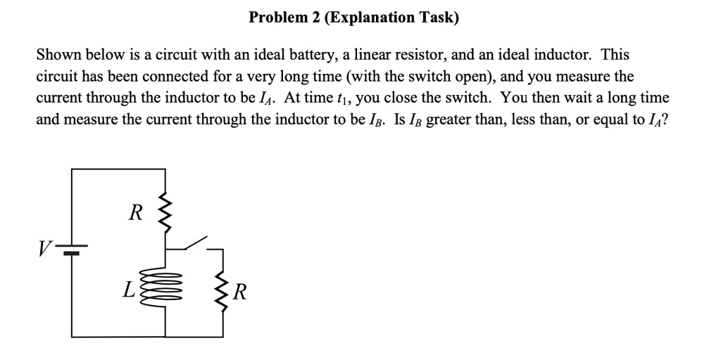
SOLVED: Problem 2 (Explanation Task) Shown below is a circuit with an ideal  battery, a linear resistor; and an ideal inductor This circuit has been  connected for a very long time (with
SOLVED: Problem 2 (Explanation Task) Shown below is a circuit with an ideal battery, a linear resistor; and an ideal inductor This circuit has been connected for a very long time (with

Activity: Inductor Self Resonance [Analog Devices Wiki]

Equivalent circuit for an ideal inductor in terms of the incremental... |  Download Scientific Diagram
Equivalent circuit for an ideal inductor in terms of the incremental... | Download Scientific Diagram

Solved Non-ideal inductors may have significant resistance. | Chegg.com

HCMA Automotive inductor | Low EMI, alloy powder | Up to 68 uH inductance |  Overview | Eaton
HCMA Automotive inductor | Low EMI, alloy powder | Up to 68 uH inductance | Overview | Eaton